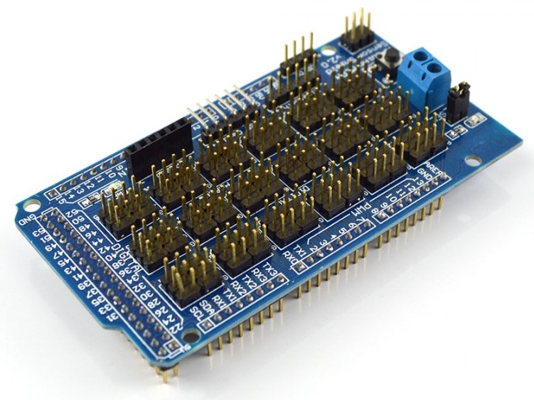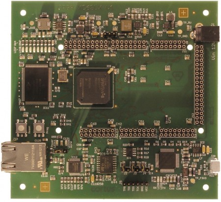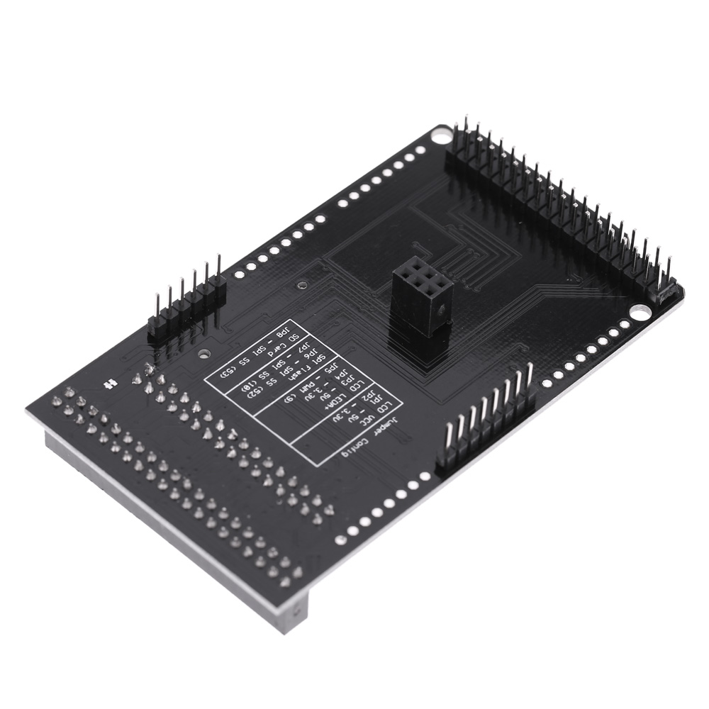

But it is also powered from 3.3v, so likely the outputs would be fine for a Due. This may not have 5v tolerant inputs, as it appears to use level translation on the input side. The Ethernet Shield V1 was based on the W5100 chip. It's unfortunate that the shield documentation doesn't seem to say anything about compatibility, but worth noting the the Ethernet Library has some specifics for the SAM family of chips one of which is used on the Due. However, you should review the the full schematics and make your own determination that these are applicable to the specific board you plan to use and do not place 5v level on any signal the Due could not accommodate. A very quick look isn't showing any glaringly obvious uses of 5v levels on the board in a place where a 3.3v Arduino derivative wouldn't expect them. Of course the shield is more than just the chip.

In other words, the core of it already is a 3.3v device, just one that can tolerate connection to a 5v Arduino. TIP: Considering the high pin count of the DUE, we recommend only soldering the headers you need for your project as this makes the board more manageable in terms of mating, not bending pins, etc.The Arduino Ethernet shield (or at least V2 of it) is based on a W5500 chip which itself features "3.3V operation with 5V I/O signal tolerance".


This is provided as a kit, meaning you will have to solder the stackable headers in to the board.


 0 kommentar(er)
